MECHANICAL PROJECTS
Overview
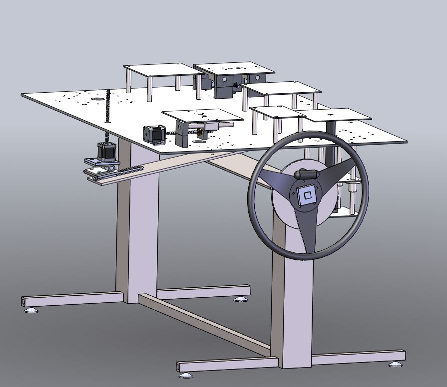
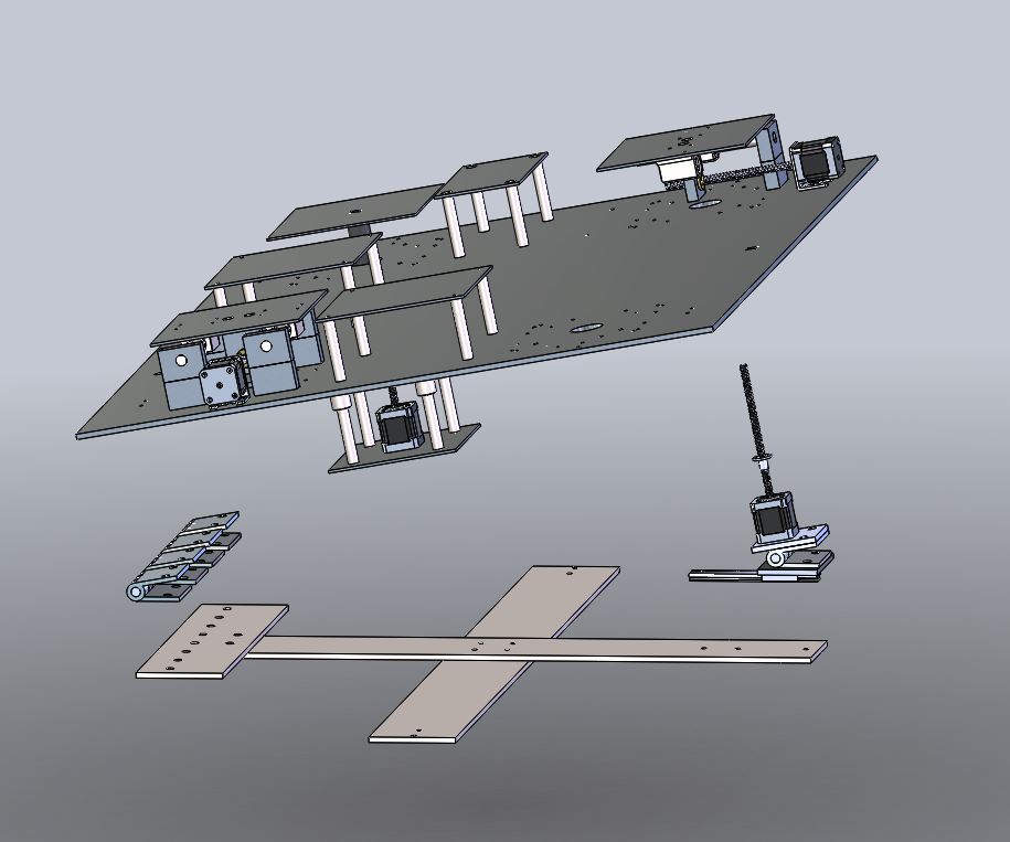
Researchers at the Advanced Medical Technologies Laboratory (AMTL) at the University of Colorado Boulder are working to develop a robotic capsule device to replace the colonoscope used in colonoscopies today. A full-scale model of the environment and potential environmental disturbances will allow for testing of the robot's control. It is desired to produce viscoelastic haustral folds of the interior of the colon, as well as simulate disturbances caused by patient breathing, shifting, and peristaltic motions. Our disturbance simulator design is shown to the right. The colon (not shown in the figure) will be attached to the top plates of this system.
Locking Pin System
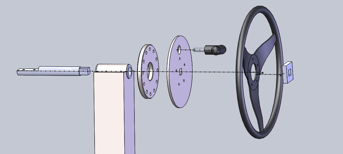
In order to mimic axial rotation along the body full rotation of the colon is implemented using a wheel locking system. The diagram below shows the setup of this system.
The most left steel disk will be fixed to the base structure allowing the second steel disk and wheel to be free moving. A steel rod (on left) goes through the bushing attached to the legs of the table and then keys into the second steel disk. This steel disk will connect to a large wheel. The steel disk will also have a milled section to house a pull pin locking system. For use the pull pin must be pulled out of the hole to enable rotation. The user is then able to rotate the system using the wheel. Once a desired angle is reached, the pull pin is allowed to return to the nearest hole. The system will be held together by a final female key component (far right). This final aluminum part will screw onto the rod, holding the system together axially. Overall, it will simulate the patient lying on one side and completely rolling over to their other side.
Clapper Actuation
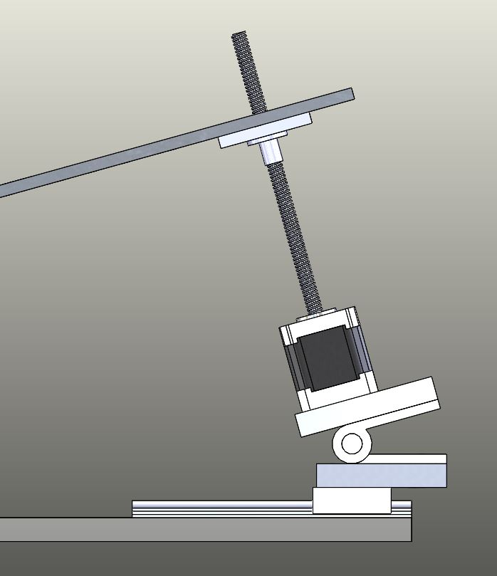
In addition to the entire 90-degree rotation of the base plate more precise actuation of the end of the plate is desired to help represent crunching motion of the colon. The clapper design (shown below) consists of a stepper motor attached to a hinge. This is then mounted on a rail that gives the structure two degrees of freedom and allows the axis of rotation to be moved from the center of the plate to the edge.
Translation Stages
A fully automated controlled device is desired for the base of the simulator to instill disturbances on the synthetic colon. These disturbances include motion due to patient shifting, compression due to breathing, and stretching due to peristalsis. The disturbances must be able to be varied in length and amplitude to create an environment that could simulate many different scenarios. This is achieved by including motor driven X, Y and Z translations at different points of the colon.
X and Y Translation:
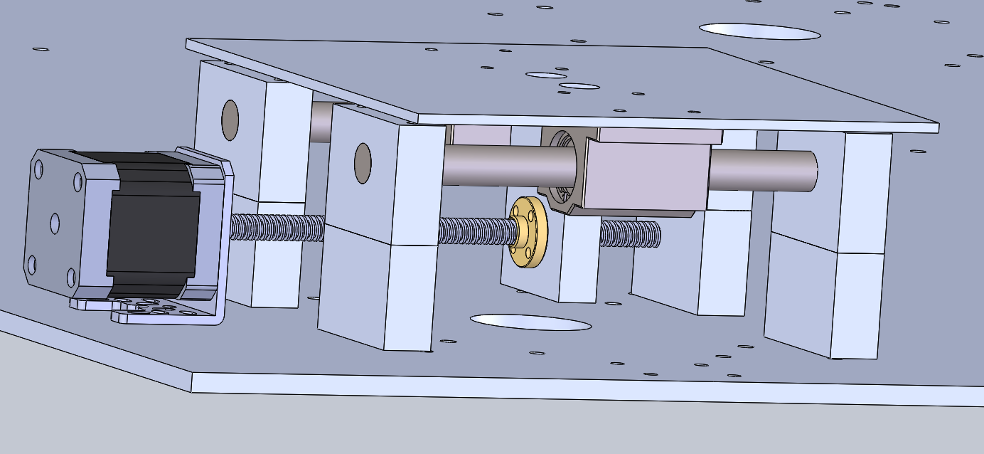
For simplicity, the same actuation design was used for all X, Y and Z translations. The design (shown below) of the X or Y translation stage uses a lead screw in correlation with parallel guide rails consisting of bearings and rods.
A lead screw stepper motor is mounted horizontally onto the top base plate housing parallel steel guide rails. The guide rails contain linear bearings used to guide the colon plate. Finally, a manufactured part is fastened onto the lead screw nut which attaches to the colon plate. This assembly allows for smooth motion in the X and Y directions in order to instill stretching and compressing motions on the colon.
Z Translation:
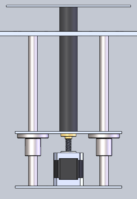
To achieve Z translation the X/Y design is rotated and mounted underneath the top base plate via steel support rods. The support rods act as guide rails for flanged linear bearings. An aluminum plate is attached to an aluminum sheath along the length of the lead screw and is mounted above the linear bearings. Connection of this plate to the steel supports ensures only linear motion and eliminates rotational motion. In addition it attaches to the lead screw nut allowing for the motion to be created. This design specifically allows for another degree of freedom of patient shifting, focusing more on mimicking patient breathing.
Mold Core
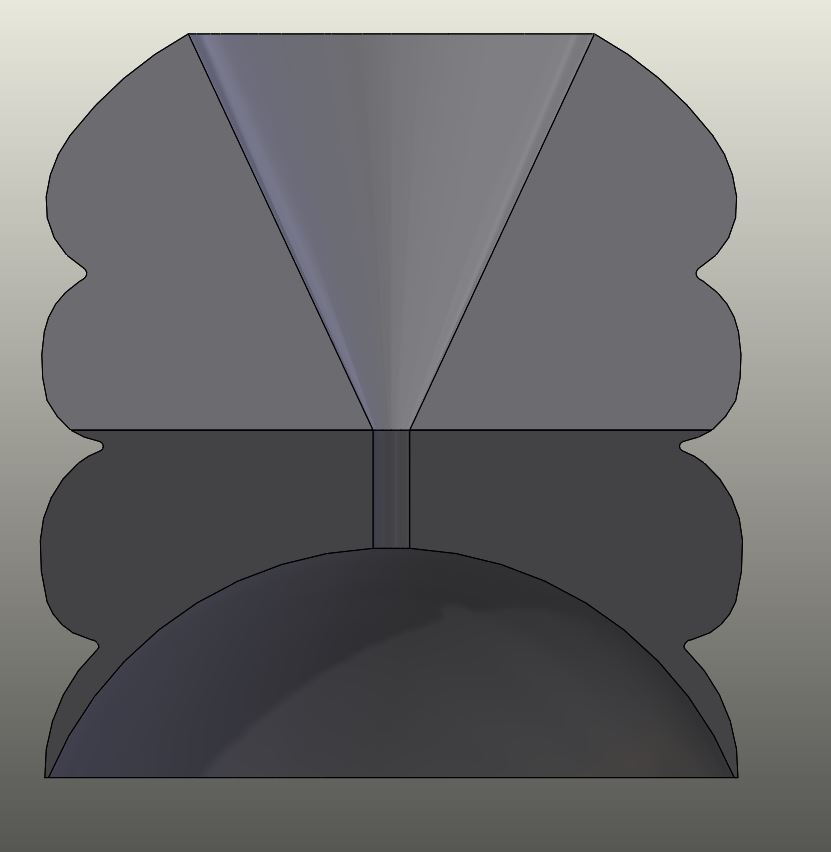
To meet the requirement of casting an anatomically accurate colon differentiated haustral folds need to be represented. This is achieved by 3D printing an inner mold core (shown right) of a rounded ball and cup system. This design is modular so each piece fits onto one another and can be beaded together with a wire with the hole shown going through the middle of the core. This allows the system to be easily positioned into the desired shape of the colon to mold the full length of the colon in a single pour.

Overview
It was assigned to construct a drill powered bike with the requirement of the bike having at least 3 wheels. Our design consisted of maintaining an existing bike structure while attaching a bike trailer to the end for the third wheel requirement. Our design focused on simplicity and functionality.


The bike was powered by attaching a drill above the back tire. This allowed for close access to the bike gears and kept the drill out of the way of the rider. This placement also allowed for the bike chain to be tensioned by the position of the bike seat.
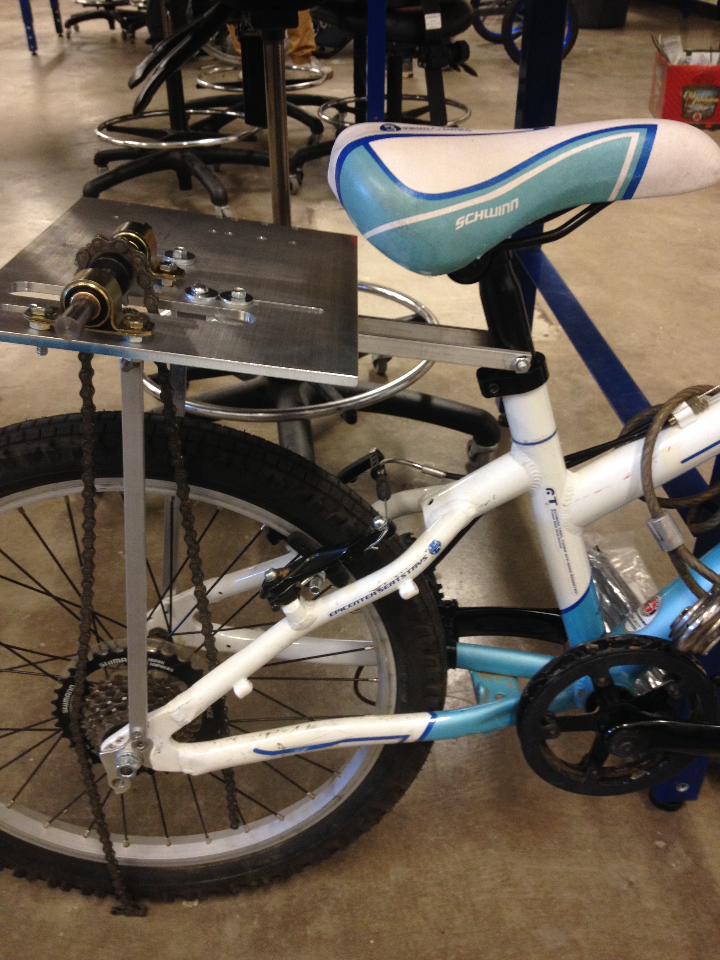
An aluminum rod was inserted into the drill to act as the drive shaft. This aluminum rod was put through two vibration damping bearings to reduce dampening while in use. The drive shaft also had a bearing sprocket where the connection to the chain came allowing for the drill to turn the chain and therefore power the bike. As well, set screw shaft collars were used to keep the sprocket in place.

Overview
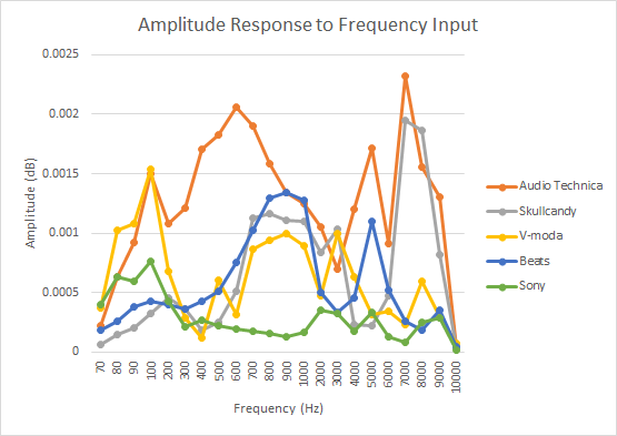
Headphones aren’t designed for accuracy as much as they are designed so that layers of tones sound nice to the end user. By measuring the amplitude response of headphones conclusions can be made to determine if there is a correlation between frequency input and amplitude response for different headphone models. It is expected for the amplitude to peak at different frequency tones by determining if there is a correlation between the model of headphone and the amplitude at which it peaks.
The System
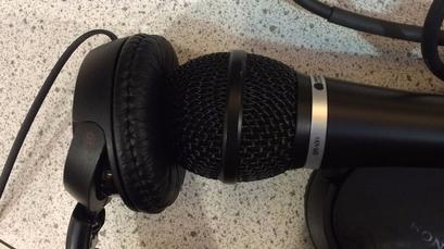
The system consists of putting a microphone against the output sound of different pairs of headphones (shown below). The signal from the microphone is then input into a non-inverting amplifier circuit. This was to ensure a quality signal was recorded. This signal was then read via an oscilloscope.
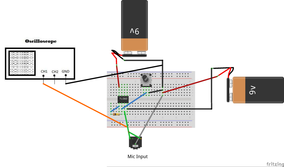
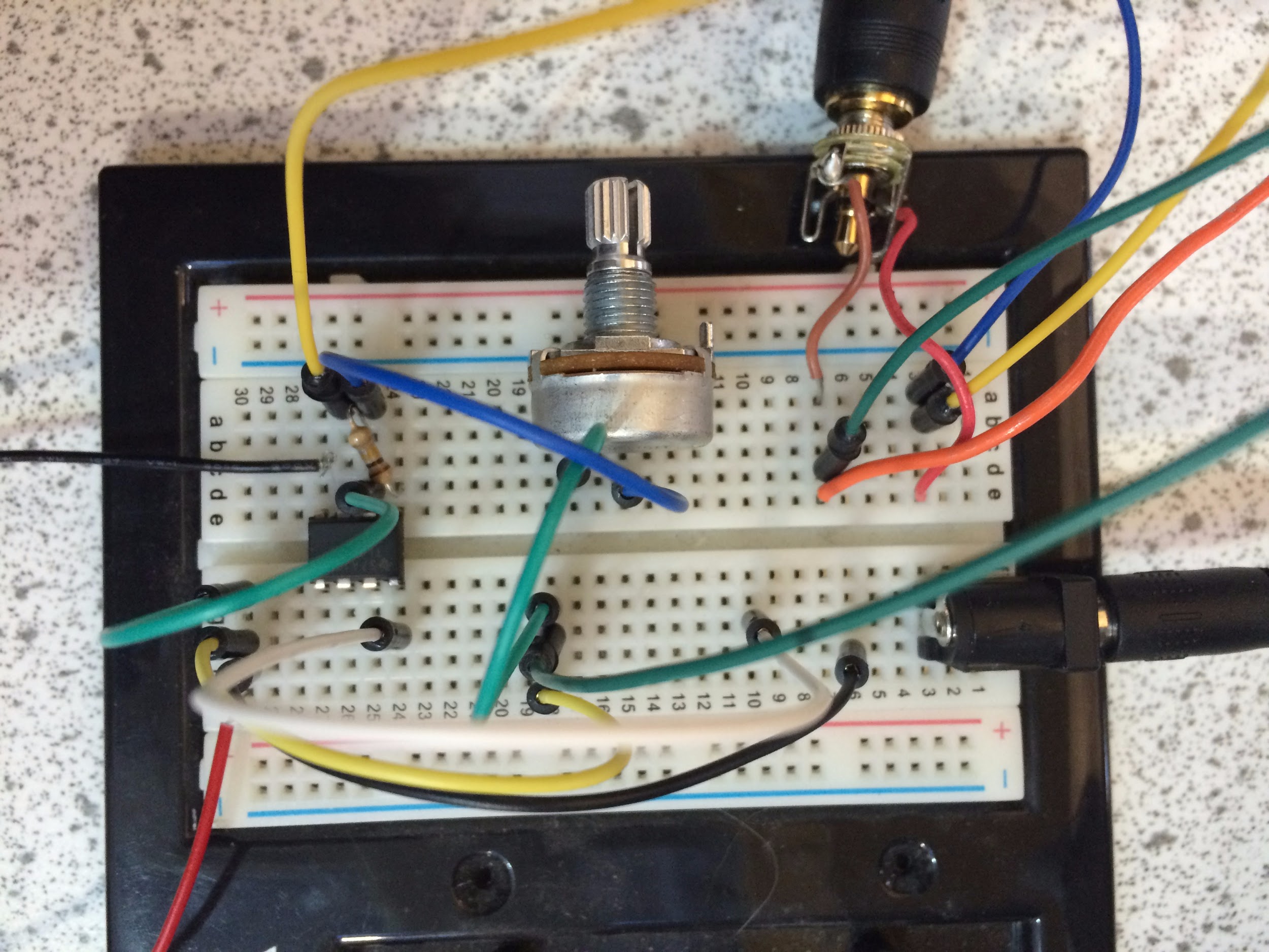
The setup of the circuit (shown on right) contains an audio jack for the microphone input and a potentiometer to vary the gain of the signal. The physical circuit built and used can be seen on the far right.
Acquiring the Signal
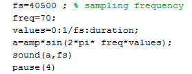
Frequencies output on the headphones were generated in MATLAB ranging from 70-10000 Hz.
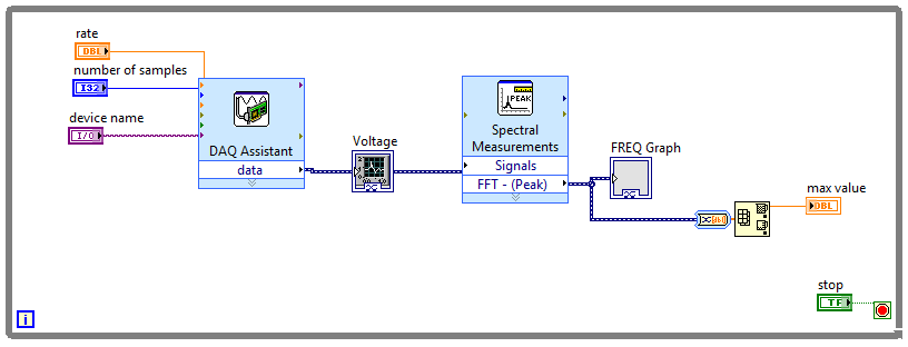
LabView was used to record the voltage signal and convert it from voltage to amplitude using a Fast Fourier Transform.
Results
Variances between sets, determined by F-Tests, were significantly different for every pair except for the Audio-Techinca - Skullcandy pair and the V-Moda - Beats pair. There appears to be a trend of increasing frequency response at 100 Hz, 900 Hz, 5000 Hz, and 8000 Hz and decreasing frequency response at 400 Hz, 1000-4000 Hz, and 6000-7500 Hz. The Sample, Column, and Interaction P-values yielded are all significantly less than the significance value of a=0.05, indicating that the frequency responses for each headphone are significantly different, even at specific frequencies.
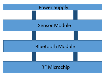
The smart golf ball will be embedded with micro-electronic components that integrate aspects of the game of golf into the palm of one’s hand. A smart phone will be able to communicate with the golf ball to tell the player statistics about their game and help them track where their golf ball landed. The smart golf ball would allow for the game of golf to become automated allowing for faster play, reducing number of penalty strokes and helping the golfer improve their game. In order for the golf ball to incorporate all of these aspects the golf balls core must be embedded with a variety of components. These components include a sensor module, power supply, bluetooth chip, and RFID chip. To reduce the overall size these devices would need to be 3D packaged together (shown below). The microsensors could be used to calculate the final score, the embedded RF chip would locate the final location, and the bluetooth module would be used to send the data.
Click here for a full report of my project.
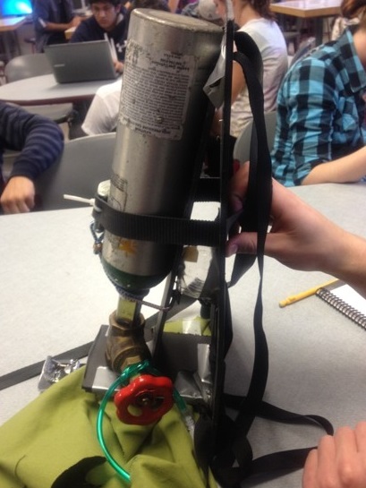
Owen Weekly is a young boy of two and a half years. He has a pediatric interstitial lung disease that causes him to need supplemental oxygen while sleeping and most times when he is awake. Owen’s parents, want to take Owen hiking and skiing to experience those sports loved by Coloradans. However, Owen’s tank is heavy and cumbersome, requiring that his parents carry the tank with a long hose extension. The design objective was to create something portable that would keep Owen safe while stabilizing the tank and distributing the weight around Owen’s hips, keeping him more stable and less likely to get hurt. The designed frame distributes the weight of the oxygen tank properly to prevent any back injuries and gives Owen the ability to carry the backpack. The first image on the right shows the machined frame holding the oxygen tank. The second image shows Owen enjoying his new backpack!